1. Load and trace a floorplan
This is the step people get stuck on, so it gets the longest page. The good news is that most plans need one slider and nothing else.
What you are actually doing
Your floorplan is a picture. To the app it is just dark and light pixels. It has no idea which dark pixels are a load-bearing wall and which are the number "3600" printed next to a dimension line.
Tracing is how you tell it. The process has two halves, and they are separate on purpose:
- The mask. Sliders decide which pixels count as wall. This updates live, and everything currently counted turns red on the canvas.
- The trace. A button turns that red mask into actual wall lines with thicknesses. This is much slower, which is why it does not happen on every slider move.
If you change a slider, press Trace walls again
Sliders only change the red overlay. Until you press the button, the wall lines underneath are still from the previous settings.
The one slider that matters
Min stroke half-width.
Architectural drawings use stroke weight to mean something. Walls are drawn thick. Dimension lines, hatching, lettering, furniture symbols and door swings are drawn thin. This slider deletes every stroke thinner than twice its value, which throws away the thin clutter and keeps the walls.
Raise it until the red overlay stops highlighting text and dimension lines. Then stop. If you raise it too far you will start eating thin partition walls, which is worse than leaving a bit of clutter.
Watch the Mask coverage figure in the statistics panel as you drag. On a typical residential plan, walls are somewhere around 2 to 8 percent of the image. If you are at 30 percent, something large is being counted that should not be.
The other controls, roughly in the order you might need them
Region tools
- ROI draws one box, and everything outside it is discarded. Use it for the title block, the north arrow, the legend, the scale bar, and anything else printed in the margin.
- Exclude paints out rectangles inside the ROI. Use it for detail drawings, stair symbols, section markers and any furniture drawn as heavily as a wall.
Reach for these before you fight the sliders. A single exclude box is usually cleaner than a slider setting that compromises everywhere else.
Gap bridging
Wall strokes get broken by door swings, by scanner dropouts and by the slider above. Gap bridging fills notches narrower than twice its value, so a wall stays one piece rather than falling apart into fragments.
If your traced walls come out as a dashed line of short segments, raise this.
Max stroke half-width
Off by default. It removes strokes thicker than twice its value, which is what you want for plans where rooms are filled in solid, or where furniture is drawn as filled blocks.
It has a side effect worth knowing: it can punch holes where two walls meet, because a junction is locally thicker than either wall. If you turn this on, raise the gap bridging alongside it.
Threshold method
- Otsu picks one brightness cut for the whole image. Best on a clean, evenly lit plan, which includes anything exported from CAD.
- Adaptive picks a cut per neighbourhood. Use it on a photograph of a plan, or a large scan where one corner is darker than the other. The window radius must be clearly larger than your thickest wall stroke, or the walls get hollowed out into outlines.
- Manual lets you set the cut yourself, for when neither of the above does what you want.
Invert input
For plans drawn light on dark: negatives, and some CAD exports. If your first attempt highlights everything except the walls, this is the control you want.
Brightness, contrast, gamma, denoise blur
Ordinary image adjustments, applied before thresholding. Useful on a phone photo of a printed plan. Skip them on a clean file.
After tracing: the vector controls
Once you have wall lines, a second group of settings controls how those lines are tidied up. The defaults are good. Change them if you see a specific problem.
- Simplify tolerance. Higher means fewer, straighter segments. Raise it if your walls come out visibly wobbly.
- Spur removal. Thinning leaves little dead-end stubs at wall ends. This deletes branches shorter than the value you set.
- Vertex welding. Endpoints closer together than this become one shared corner. This matters more than it sounds: the app treats a wall end that no other wall meets as a diffracting edge, so unwelded corners create diffraction edges that do not exist.
- Orthogonal snap. Pulls nearly-axis-aligned walls exactly onto the axis. Turn this off if your building genuinely has angled walls, or it will straighten them for you.
- Collinear merge. Joins two segments that meet almost straight into one.
- Min wall length. Drops fragments shorter than this.
How to tell you are done
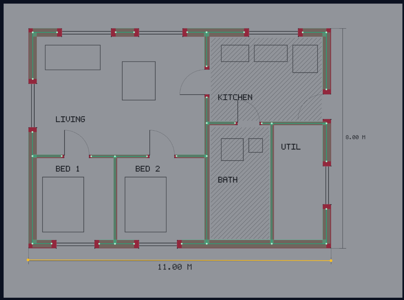
What a finished trace looks like. Green centrelines carrying the measured wall thickness, red markers where walls meet, and the yellow calibration line along the printed dimension. Everything thin has been dropped: the lettering, the furniture, the hatching in the bathroom, and the dimension lines themselves.
Look at the traced result and ask three questions.
Is every wall there? A missing wall is the worst failure mode, because the map will look fine and be optimistic. Walk the outline of each room in your head and check it is closed.
Are there walls that do not exist? Usually leftovers from furniture or a detail drawing. Delete them in the model editor later, or add an exclude box and re-trace.
Do the thicknesses look right? The statistics panel shows the measured thickness range. If it says every wall in your building is 60 mm, your scale is probably not set yet, or the tracing is finding stroke outlines instead of strokes.
When it just will not work
Some plans fight back. In rough order of what to try:
- Draw an ROI around one room and get that right first. It is much easier to see what a slider is doing on a small area.
- If the plan has both thick outer walls and very thin partitions, favour keeping the partitions. You can delete spurious walls by hand in the model editor, but you cannot invent a wall the tracer never found without drawing it.
- If the drawing is hatched, the hatching is often the same weight as thin partitions. Exclude boxes are usually faster than tuning.
- If nothing works, draw the walls by hand in the model editor. On a small flat this takes about five minutes and gives a perfect result.
If you hit a plan the tracer handles badly, please open an issue with the image attached. That is genuinely useful and it is how the defaults get better.
Next
Set the scale, which is the step that decides whether any of the numbers mean anything.